O electric bus drive system configuration generally includes: power battery system assembly, drive motor and controller, motor controller, VCU vehicle controller, electric air pump for braking system, electric hydraulic steering pump, electric air conditioner and defroster, and some auxiliary function appliances. The various components of the system assembly need to be matched, designed and selected according to the specific parameters of the vehicle.
In response to different purposes of different regions and different routes, there are many different lengths of electric buses, including 6 meters, 8 meters, 10 meters, and even 18 meters. How to configure the drive system for electric buses of different lengths?
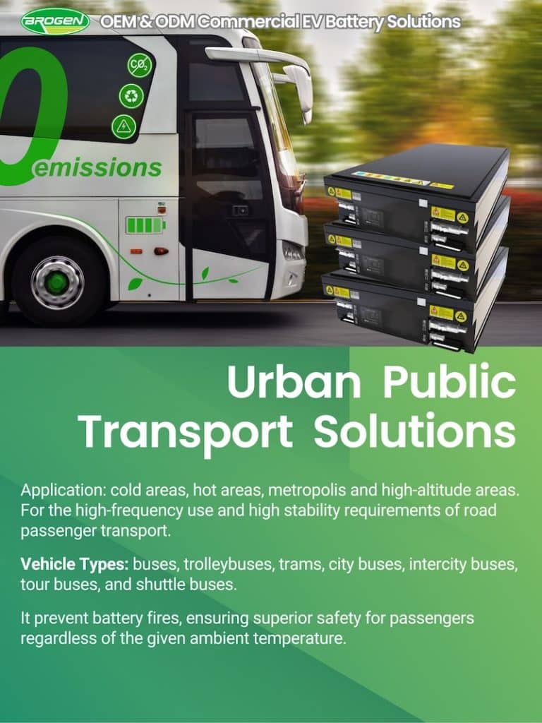
The 8-meter pure electric bus is designed primarily for urban public transportation. It typically features a gross vehicle weight (GVW) of 12 tons, a top speed of 69 km/h, and a maximum gradeability of 20%. The system configuration must be customized based on operational conditions such as route topology, passenger load, and regional climate.
This article presents the complete configuration architecture of the electric powertrain and auxiliary systems, offering insights for OEMs, retrofitting companies, and integrators aiming to enter the electric bus sector.
Power Battery System for 8-Meter e-Bus
The power battery system is the heart of the electric bus and includes:
- Battery packs housed in protective enclosures
- PDU
- BMS (Battery Management System)
- High-voltage harnesses
- Low-voltage communication cables
Key Technical Parameters
Voltage Platform: Typically 576V–750V DC.
Battery Capacity: Depends on operational requirements such as daily mileage, ambient temperature, use of air conditioning, and long-term degradation (15% buffer recommended over 5 years).
8 meter bus Battery Capacity Planning (Urban Duty Cycle)
For a 200 km daily range: ~160 kWh (no A/C) to ~220 kWh (with A/C)
For a 250 km daily range: ~200 kWh (no A/C) to ~270 kWh (with A/C)
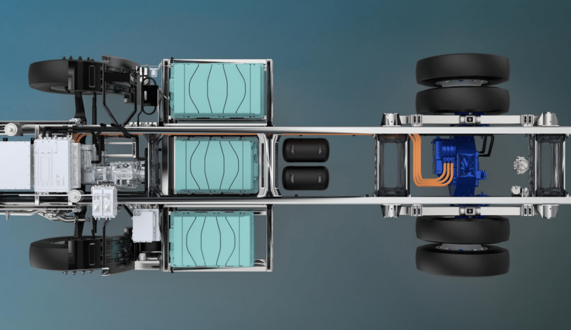
Battery Placement Options
Step-floor buses: Batteries mounted between front and rear axles or on rear platform
Low-floor buses: Batteries placed on the rooftop for better accessibility and space optimization

Direct Drive Motor and Electric Drive Axle
The drive system directly influences the vehicle’s performance. Two mainstream architectures are available:
Option 1 : Direct Drive Motor
Rated Power / Peak Power: 75 kW / 135 kW
Rated Torque / Peak Torque: 650 Nm / 1600 Nm
Suitable for step-floor buses; offers mature and cost-effective integration.

Option 2: Wheel-Side Electric Axle (see below picture)
Rated Power / Peak Power: 2 × 60 kW / 2 × 120 kW
Rated Torque / Peak Torque: 2 × 145 Nm / 2 × 400 Nm
Ideal for low-floor buses; enhances floor flatness and passenger comfort.
Each motor type comes with its dedicated inverter controller. Select the system based on route gradients, passenger load, and desired NVH (Noise, Vibration, Harshness) performance.

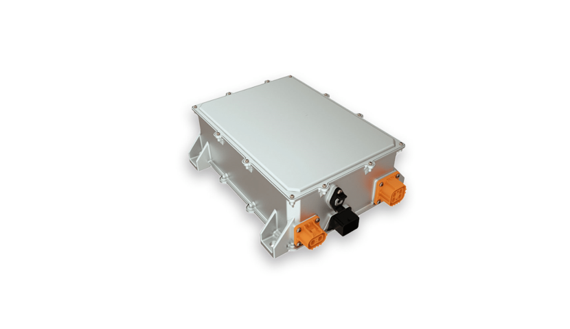
Integrated Controller (Multi-in-One Unit)
This unit consolidates: DC/AC inverters for the air compressor and steering pump, DC/DC converter for low-voltage subsystems, Optional integration with motor controller.
Voltage Platform: DC 576V–750V
Key Parameters : Input/Output voltage and current ratings must align with motor and battery specifications
This controller also supports power supply and control for high-voltage auxiliaries like HVAC systems.
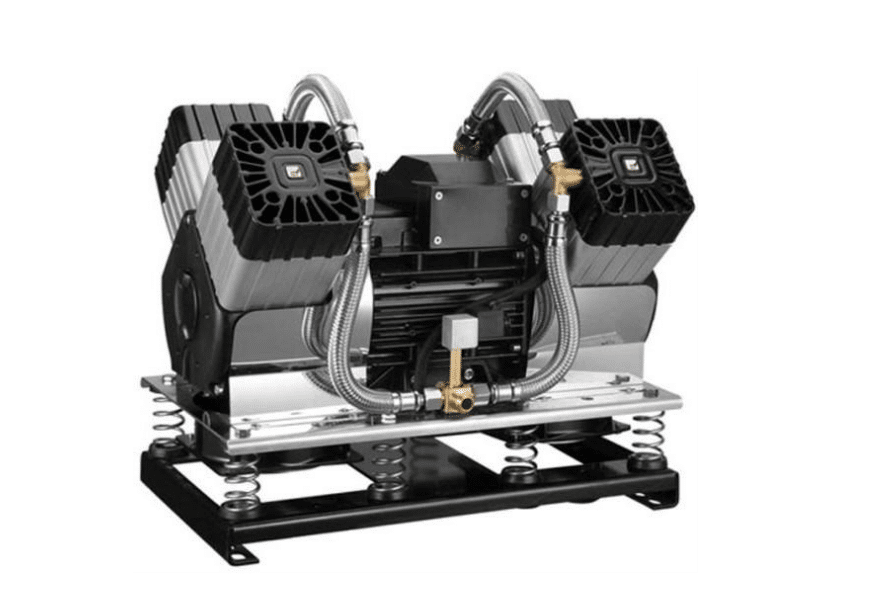
Compressor de ar elétrico
Provides pressurized air for service brakes and pneumatic doors
Typical Configuration: 3 kW rated power
Key Specs: Maximum pressure and airflow volume as per system requirements
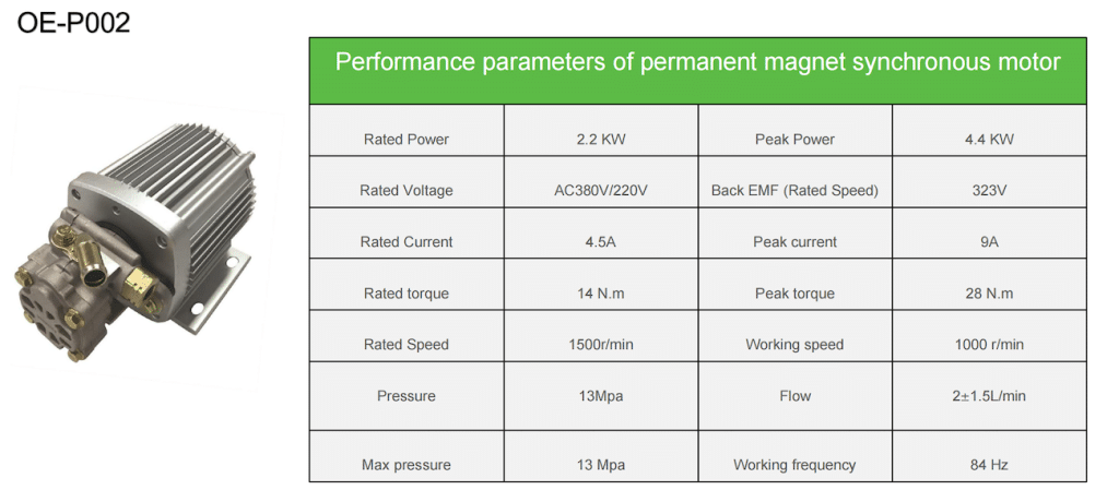
Electric Power Steering Pump
Ensures smooth and responsive steering assistance. A dual-source (high-voltage and low-voltage backup) setup is recommended for enhanced reliability.
Typical Configuration: 2 kW rated power
Key Specs: Flow rate and pressure optimized for an 8-meter chassis
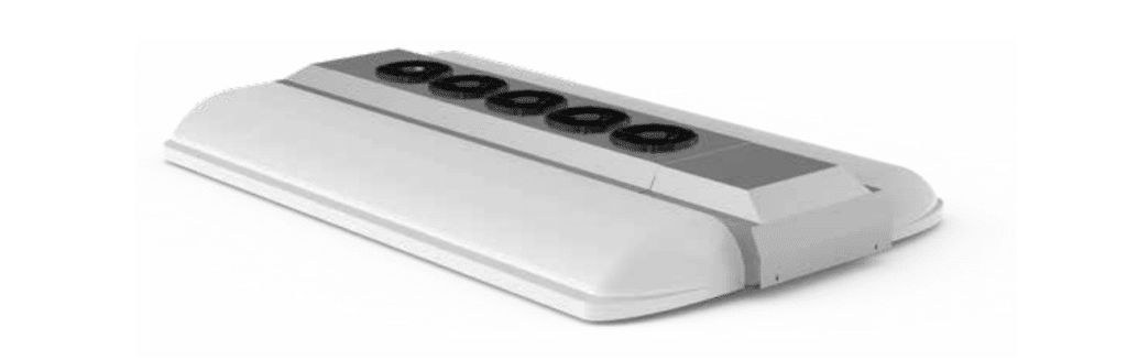
Electric HVAC System and Defroster
Key Considerations:
Cooling and heating capacity should match local climate conditions.
Must be compatible with the high-voltage platform.
HVAC system accounts for up to 30% of total energy consumption in hot climates.
It is essential for passenger comfort and windshield visibility. The current trend for electric buses is to integrate the air conditioning system and the battery cooling system to form a complete vehicle thermal management system.
ATS Cooling System
Active Thermal System (ATS) manages heat generated by the drive motor and inverter.
Cooling performance must be tailored to the thermal load of the drive unit under full-load conditions.
Components
- Electronic water pump
- Radiator fan assembly
- Smart controller module
In Summary
| 8 meter electric bus | Configuração | |
| Battery System | For a 200 km daily range: ~160 kWh (no A/C) to ~220 kWh (with A/C) | For a 250 km daily range: ~200 kWh (no A/C) to ~270 kWh (with A/C) |
| Powertrain System | Direct Drive Motor Rated Power / Peak Power: 75 kW / 135 kW Rated Torque / Peak Torque: 650 Nm / 1600 Nm Best suited for step-floor buses; offers mature and cost-effective integration. | E – Axle Rated Power / Peak Power: 2 × 60 kW / 2 × 120 kW Rated Torque / Peak Torque: 2 × 145 Nm / 2 × 400 Nm |
| Controlador do motor | DC 576 V – 750 V | |
| Compressor de ar elétrico | 3 kW rated power | |
| Electric Power Steering Pump | 2 kW rated power |
Entre em contato com a Brogen
A Brogen é uma fornecedora líder de soluções de ev para veículos comerciais e barcos. Entre em contato com nossos especialistas em inquiry@brogenmotors.com. Prometemos entrar em contato com você em até dois dias úteis.
Para obter as últimas notícias, consulte Linkedin da Brogen. Para mais vídeos, clique em Youtube da Brogen.